Overview
Scope
The goal of this project is to develop a robotic leg test platform to perform experiments on various actuation and control systems. This project is entirely self-funded and independent. I had the ideas back in August of 2025 and have recently had the funds to start developing it. Additionally, I have had a lot of success using Cursor to help me develop programs for projects either faster or better than my skill level allows, but so far in this project I have been doing everything on my own to push myself to get more comfortable with programming.
Planned Experimental Goals
-
Test Passive and Active Adaptive Transmissions' Efficiency Compared to
Traditional Drive Trains By Attempting to Keep Motors at More Consistent
Operating Conditions Throughout the Gait
- The plan is to use a modified version of a Zero Ratio-like CVT for passive adaptivity, and a Toyota Planetary CVT inspired system for active adaptivity
- Take my experience with computer vision, specifically MediaPipe, and see how well I can create teleoperation based on my own legs' motion caught on camera
-
Experiment with non-constant center of rotation at the knee joint (like a
real human knee) to see if it meaningfully produces a gait more similar to
that of a human.
- Not many walking robots I see include this, and I think it could meaningfully produce a gait that looks less robotic / falling forward
Media
Everything Working Perfectly First Try
Getting a feel for both the motor's default PID controller and my custom 3D printed parts.
Suspended Test of Mock Leg Design
Setting up both the second motor and new Mean Well power supply
Parker FEA
This is the planned testing platform for the leg. The intent is to guide it on a planar trajectory and allow the leg to skate through the swing phase of the walking gait. I was unhappy with the fixed casters in my local hardware stores. I figured I would likely have to modify whatever I bought to attach to the aluminum extrusion anyway, so I made my own for cheap and wanted to make sure they could handle some moderately dynamic loads. I suspended ~35 lbs from the test platform and gave it a shove.
Aluminum Extrusion Linkages
Getting a sense of the new aluminum-extrusion-based leg design after I was unhappy with how difficult it was to locate everything correctly on the PVC version. Additionally, hand testing the planned belt drive system.
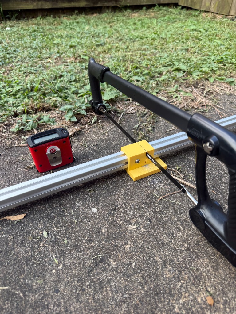
3D printed jig for better cuts on aluminum extrusion
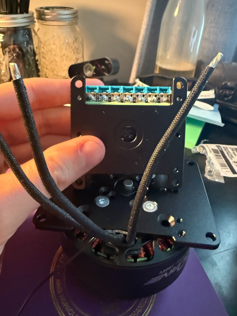
ODrive S1 and M8325s Motor Kit
My plan right now is to use two ODrive M8325s motors for both the knee and hip, along with the S1 motor controllers and Hall-effect-based encoders. I will likely need more motors in the future, but for these primary joints being the focus of my project I wanted motors with good torque outputs and sensing I can easily record and use. Additionally, they have a lot of prebuilt integration like ROS 2, and I know I can go through James Bruton's videos on YouTube and GitHub for help on actually using them.
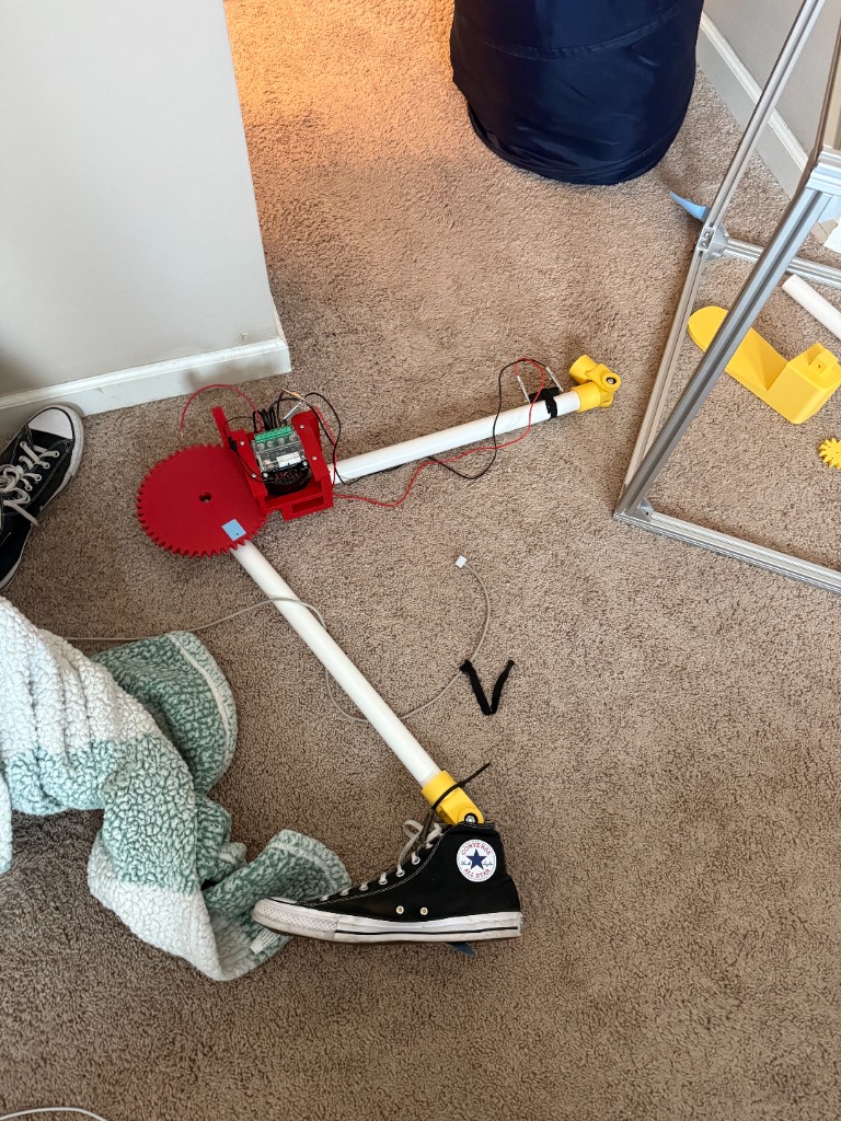
Mock Leg Design
I threw together this leg to get a sense of the general design direction I wanted to go with for the actual leg. The gear drive here was simply to A) Test 3D printed gears, and B) make it move. I was initially optimistic about the PVC linkages, but found accurately locating the motor to the knee joint requires an excessive amount of 3D printing. I was incredibly happy with my hinge design though. I managed to get very smooth low-friction planar rotation using some cheap bearings off of Amazon I press fit in.
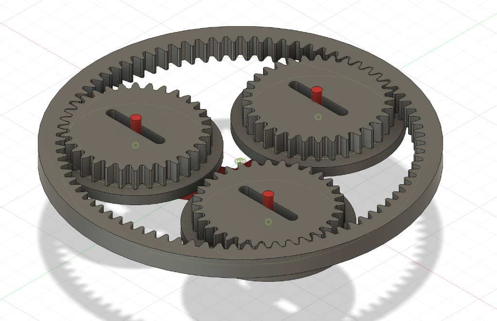
Attempting to reverse engineer the Zero Ratio CVT
Early CAD model for the coupled planetary gear set inspired by
https://www.varionova.tech/technology.html